If you have ever wanted to deploy an ESP32 sensor node in a farm field, on a rooftop, or at a remote water tank, you have hit the same wall everyone does: where does the power come from? Running a cable is impractical. Replacing batteries every few weeks is tedious. The answer, especially in a country that averages 250-300 sunny days a year, is solar.
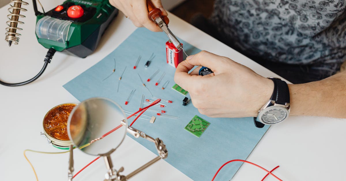
This guide walks you through designing, building, and deploying a completely self-sustaining solar-powered ESP32 IoT node. We will cover component selection, wiring, firmware with deep sleep, power budgeting with real numbers, and the practical realities of outdoor deployment in Indian conditions — from monsoon rains to monkeys.
Why Solar Power for IoT?
Three reasons make solar the default choice for remote IoT:
-
No mains power available. Agricultural fields, forest monitoring stations, highway infrastructure, water tanks on building terraces — these locations rarely have a convenient power outlet.
-
Zero recurring cost. Once deployed, a solar node costs nothing to run. No electricity bill, no battery replacements if sized correctly. A well-designed node can run for 5+ years with zero maintenance.
-
True autonomy. A solar-powered node is a deploy-and-forget system. It charges during the day, operates around the clock, and survives cloudy stretches on stored battery energy.
For India specifically, solar irradiance ranges from 4 to 7 kWh/m2/day across most of the country, making it one of the best regions in the world for small-scale solar harvesting.
System Architecture
A solar IoT node has five core components connected in series:
Solar Panel --> TP4056 Charge Controller --> 18650 Li-ion Battery --> LDO Regulator --> ESP32
| Component | Role |
|---|---|
| Solar Panel | Converts sunlight to DC voltage (5-6V) |
| TP4056 Module | Charges the lithium battery safely with CC/CV profile |
| 18650 Battery | Stores energy for night and cloudy periods |
| LDO Regulator | Steps down battery voltage (3.0-4.2V) to stable 3.3V |
| ESP32 | Your microcontroller running the application firmware |
Let us look at each component in detail.
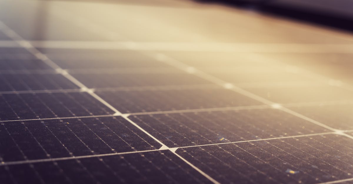
Choosing the Right Solar Panel
For ESP32 projects, you need a panel that outputs 5V-6V open circuit voltage (Voc). This feeds the TP4056 which needs at least 4.5V input to charge a lithium cell.
Panel Sizing Guide
| Use Case | Panel Rating | Typical Size | When to Use |
|---|---|---|---|
| ESP32 with deep sleep, wakes every 15 min | 6V / 1W | 110 x 60 mm | Sensor reading + short MQTT publish |
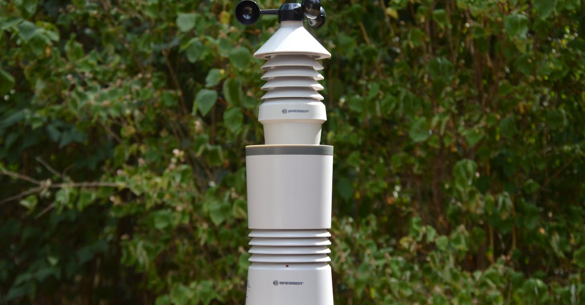
| ESP32 with WiFi active 30s every 5 min | 6V / 2W | 136 x 110 mm | Weather stations, basic telemetry |
| ESP32 with WiFi active several minutes per hour | 6V / 3W | 145 x 145 mm | Camera triggers, OTA updates, heavy data |
| ESP32 with LoRa (no WiFi) | 6V / 1W | 110 x 60 mm | LoRa is very low power |
Key specifications to check:
- Voc (Open Circuit Voltage): Should be 6-7V. Avoid 12V panels for direct TP4056 charging — the TP4056 maximum input is 8V, and 12V panels can output 18-21V Voc under no load and destroy the chip.
- Isc (Short Circuit Current): A 6V/1W panel delivers roughly 170mA. A 6V/3W panel delivers roughly 500mA. The TP4056 charges at up to 1A, so even a 3W panel will not overdrive it.
- Cell type: Monocrystalline panels are 2-3% more efficient than polycrystalline in the same footprint. Worth the small price difference for compact nodes.
Practical tip: Buy a panel rated at least 1.5x your calculated requirement. Real-world output is always lower than rated — dust, angle, haze, and aging all reduce yield.
Battery Selection: 18650 Lithium-Ion
The 18650 cell is the standard for solar IoT. It is inexpensive, widely available, has excellent energy density, and thousands of charge cycles.
What to Look For
| Specification | Recommended | Why |
|---|---|---|
| Capacity | 2600-3500 mAh | Higher capacity = more night/cloudy runtime |
| Chemistry | Li-ion (not LiFePO4) | 3.7V nominal matches ESP32 voltage needs |
| Protection | Built-in PCB preferred | Prevents over-discharge below 2.5V which kills cells |
| Brand | Samsung, LG, Sony/Murata, Panasonic | Avoid unbranded cells claiming 9900mAh — these are always fake |
Discharge Curve
A fully charged 18650 sits at 4.2V and drops to about 3.0V when empty. The discharge curve is mostly flat around 3.6-3.7V for 80% of the capacity, which is convenient — it means your LDO has a relatively stable input for most of the cycle.
Critical warning: Never discharge an 18650 below 2.5V. This causes irreversible damage to the cell chemistry. Always use a protection circuit (the DW01A on the TP4056 module handles this).
How Many Cells?
For most ESP32 deep-sleep applications, one 18650 cell (3000-3500 mAh) is sufficient to last through the night and one full cloudy day. If you need to survive 2-3 cloudy days (important for monsoon season), use two cells in parallel to double the capacity to 6000-7000 mAh.
Never connect 18650 cells in series for an ESP32 project — you will get 7.4V or higher which requires a buck converter and wastes energy.
TP4056 Charge Controller
The TP4056 module is a single-cell lithium-ion charger that costs under 30 rupees and handles the entire charge cycle automatically:
- CC phase: Charges at constant current (default 1A, set by the PROG resistor) until the cell reaches 4.2V
- CV phase: Holds voltage at 4.2V while current tapers down
- Termination: Stops charging when current drops below ~10% of set current
Module Variants
There are two common TP4056 modules. Always use the one with battery protection:
| Module | IC(s) | Protection | Use |
|---|---|---|---|
| TP4056 only (red LED board) | TP4056 | None | Never use for unattended solar |
| TP4056 + DW01A (blue board) | TP4056 + DW01A + 8205A MOSFETs | Over-discharge, over-charge, short circuit | Always use this one |
The DW01A protection IC disconnects the battery at ~2.4V (preventing deep discharge) and at ~4.28V (preventing overcharge). It also provides short circuit protection.
Load Sharing Problem
The basic TP4056 module has a known limitation: it does not support simultaneous charging and discharging well. When the solar panel is charging the battery and the ESP32 is drawing current from the battery at the same time, the TP4056 can oscillate between charge and not-charge states, and the reported charge status becomes unreliable.
For a deep-sleep IoT node that sleeps most of the time, this is rarely an issue in practice — the ESP32 draws microamps during sleep, which is negligible. However, if your application needs to run continuously while charging, consider one of these alternatives:
- IP5306 boost module — integrated power path management
- MCP73871 — designed specifically for solar load sharing
- DIY load sharing with a P-MOSFET — a simple circuit using a P-channel MOSFET (like AO3401) to route power from either the panel or battery automatically
For most deep-sleep sensor nodes, the basic TP4056+DW01A module works fine.
TP4056 Charge Current
The default PROG resistor on most modules is 1.2k ohm, setting charge current to 1A. Since a small solar panel cannot supply 1A, the TP4056 will simply charge at whatever current the panel provides — it adjusts automatically. No modification needed.
Voltage Regulation: 3.3V LDO
The ESP32 runs on 3.3V. The 18650 battery outputs 3.0-4.2V. You need a Low Dropout Regulator (LDO) to provide a stable 3.3V.
LDO Options
| Regulator | Dropout Voltage | Max Current | Quiescent Current | Best For |
|---|---|---|---|---|
| HT7333 | 100mV | 250mA | 4 uA | Deep sleep nodes (ultra-low Iq) |
| AMS1117-3.3 | 1.1V | 1A | 5 mA | Not recommended — too high dropout and Iq |
| ME6211-3.3 | 100mV | 500mA | 40 uA | Good balance of current capacity and Iq |
| RT9013-3.3 | 250mV | 500mA | 25 uA | Widely available, solid choice |
The HT7333 is the top choice for deep-sleep IoT nodes. Its 4 uA quiescent current means it wastes almost nothing while the ESP32 sleeps. The 250mA maximum output is enough for an ESP32 in most modes, though WiFi TX bursts can briefly peak at 300-500mA. In practice, a 100uF capacitor on the output handles these transient spikes.
Avoid the AMS1117-3.3. Its 1.1V dropout means it stops regulating when the battery drops below 4.4V — which is above a full battery. It also wastes 5mA continuously just existing. It is meant for USB-powered applications, not battery nodes.
Why Not Use the ESP32 Dev Board's Built-in Regulator?
ESP32 dev boards (like the DevKitC) have an onboard AMS1117-3.3 regulator and a USB-UART chip. These consume 20-50mA even during deep sleep. For solar deployment, use a bare ESP32-WROOM module or at minimum, power the dev board through the 3.3V pin directly (bypassing the onboard regulator).
Complete Wiring
Here is the full connection diagram:
SOLAR PANEL (+) -----> TP4056 IN+
SOLAR PANEL (-) -----> TP4056 IN-

TP4056 BAT+ ---------> 18650 (+) terminal
TP4056 BAT- ---------> 18650 (-) terminal

TP4056 OUT+ ---------> HT7333 VIN
TP4056 OUT- ---------> HT7333 GND

HT7333 VOUT ---------> ESP32 3V3 pin
HT7333 GND  ---------> ESP32 GND

Add capacitors:
- 10uF ceramic between HT7333 VIN and GND
- 100uF electrolytic between HT7333 VOUT and GND (handles WiFi TX spikes)
Important: Connect to TP4056 OUT+/OUT- (not BAT+/BAT-) so the DW01A protection circuit is in the path. If you connect the load directly to BAT+/BAT-, the over-discharge protection will not work.
Battery Voltage Monitoring
To monitor battery voltage, use a resistive voltage divider connected to an ESP32 ADC pin:
TP4056 OUT+ ---[100K]---+---[100K]--- GND
                        |
                    ESP32 GPIO34 (ADC1_CH6)
This divides the battery voltage by 2, so 4.2V becomes 2.1V and 3.0V becomes 1.5V — both safely within the ESP32 ADC range of 0-3.3V. GPIO 34, 35, 36, or 39 are recommended as they are input-only pins with no internal pull-ups that would affect the reading.
Firmware: Solar-Powered Weather Station
Here is a complete example of a solar-powered weather station that wakes every 15 minutes, reads a DHT22 sensor and battery voltage, publishes data via WiFi/MQTT, and goes back to deep sleep.
#include <WiFi.h>
#include <PubSubClient.h>
#include <DHT.h>

// Configuration
#define WIFI_SSID        "your-ssid"
#define WIFI_PASS        "your-password"
#define MQTT_SERVER      "your-mqtt-broker.local"
#define MQTT_PORT        1883
#define MQTT_TOPIC       "farm/node01/weather"
#define MQTT_BAT_TOPIC   "farm/node01/battery"

#define DHT_PIN          4
#define DHT_TYPE         DHT22
#define BATTERY_ADC_PIN  34
#define SLEEP_MINUTES    15

// Voltage divider calibration
// Adjust this based on your actual resistor values
#define VDIV_RATIO       2.0
#define ADC_VREF         3.3
#define ADC_RESOLUTION   4095.0

// Objects
DHT dht(DHT_PIN, DHT_TYPE);
WiFiClient espClient;
PubSubClient mqtt(espClient);

// Convert raw ADC reading to battery voltage
float readBatteryVoltage() {
  // Take multiple readings and average for accuracy
  uint32_t sum = 0;
  for (int i = 0; i < 16; i++) {
    sum += analogRead(BATTERY_ADC_PIN);
    delay(2);
  }
  float avg = sum / 16.0;
  float voltage = (avg / ADC_RESOLUTION) * ADC_VREF * VDIV_RATIO;

  // Apply calibration offset (measure with multimeter and adjust)
  // ESP32 ADC is notoriously non-linear; calibrate per board
  voltage += 0.15;  // typical correction factor

  return voltage;
}

// Estimate battery percentage from voltage (Li-ion approximation)
int batteryPercent(float voltage) {
  if (voltage >= 4.10) return 100;
  if (voltage >= 3.95) return 80;
  if (voltage >= 3.80) return 60;
  if (voltage >= 3.70) return 40;
  if (voltage >= 3.55) return 20;
  if (voltage >= 3.40) return 10;
  return 0;
}

bool connectWiFi() {
  WiFi.mode(WIFI_STA);
  WiFi.begin(WIFI_SSID, WIFI_PASS);

  int attempts = 0;
  while (WiFi.status() != WL_CONNECTED && attempts < 20) {
    delay(500);
    attempts++;
  }
  return WiFi.status() == WL_CONNECTED;
}

bool connectMQTT() {
  mqtt.setServer(MQTT_SERVER, MQTT_PORT);

  int attempts = 0;
  while (!mqtt.connected() && attempts < 3) {
    if (mqtt.connect("solar-node-01")) {
      return true;
    }
    delay(1000);
    attempts++;
  }
  return mqtt.connected();
}

void goToSleep() {
  WiFi.disconnect(true);
  WiFi.mode(WIFI_OFF);
  esp_sleep_enable_timer_wakeup(SLEEP_MINUTES * 60ULL * 1000000ULL);
  esp_deep_sleep_start();
}

void setup() {
  // Read sensors first (while WiFi is off, saves power)
  dht.begin();
  delay(2000);  // DHT22 needs warm-up time

  float temperature = dht.readTemperature();
  float humidity = dht.readHumidity();
  float battVoltage = readBatteryVoltage();
  int battPercent = batteryPercent(battVoltage);

  // Validate sensor readings
  if (isnan(temperature) || isnan(humidity)) {
    // Sensor failed — sleep and retry next cycle
    goToSleep();
    return;
  }

  // If battery is critically low, skip WiFi to conserve power
  if (battVoltage < 3.3) {
    goToSleep();
    return;
  }

  // Connect and publish
  if (connectWiFi() && connectMQTT()) {
    // Publish weather data
    char payload[128];
    snprintf(payload, sizeof(payload),
      "{\"temp\":%.1f,\"hum\":%.1f,\"bat_v\":%.2f,\"bat_pct\":%d}",
      temperature, humidity, battVoltage, battPercent
    );
    mqtt.publish(MQTT_TOPIC, payload, true);

    // Publish battery voltage separately for monitoring
    char batPayload[16];
    snprintf(batPayload, sizeof(batPayload), "%.2f", battVoltage);
    mqtt.publish(MQTT_BAT_TOPIC, batPayload, true);

    mqtt.loop();
    delay(100);
  }

  goToSleep();
}

void loop() {
  // Never reached — deep sleep resets to setup()
}
Key Firmware Design Decisions
- Read sensors before WiFi. The DHT22 draw is tiny. Reading first means if the sensor fails, we skip the expensive WiFi connection entirely.
- Battery voltage cutoff at 3.3V. Below this, the LDO cannot regulate properly and WiFi becomes unreliable. Better to sleep and let the panel recharge.
- WiFi timeout of 10 seconds. If the access point is down, we do not drain the battery waiting. 20 attempts at 500ms each.
- MQTT retain flag set to true. So the last reading is always available to subscribers even if the node is sleeping.
- No
loop()code. Deep sleep resets the ESP32, so execution always starts atsetup().
Power Budget Calculation
This is the most important section. Get this wrong and your node dies at 2 AM on a cloudy night.
ESP32 Power Consumption
| State | Current Draw | Duration per Cycle |
|---|---|---|
| Deep sleep | 10 uA | 14 min 45 sec |
| Wake + sensor read (no WiFi) | 40 mA | 3 sec |
| WiFi connect + MQTT publish | 160 mA avg (peaks to 350mA) | 5-10 sec |
| Average over 15-min cycle | ~1.2 mA |
Let us calculate properly:
- Sleep: 10 uA x 885 sec = 8,850 uA-sec
- Active + WiFi: 160 mA x 15 sec = 2,400,000 uA-sec
- Total per cycle: 2,408,850 uA-sec over 900 sec = 2,676 uA average = ~2.7 mA
Over 24 hours: 2.7 mA x 24h = 64.8 mAh per day
Solar Panel Output in India
India receives an average of 5 peak sun hours per day (ranging from 4 in the northeast/monsoon to 7 in Rajasthan/summer).
A 6V / 1W panel outputs: 1W / 6V = 167 mA in peak sun.
Daily energy harvested: 167 mA x 5h = 835 mAh
But account for losses:
- TP4056 charging efficiency: ~85%
- Panel angle/dust losses: ~80%
- Effective daily harvest: 835 x 0.85 x 0.80 = 568 mAh
The Balance Sheet
| Parameter | Value |
|---|---|
| Daily consumption | 64.8 mAh |
| Daily solar harvest (1W panel, 5h sun) | 568 mAh |
| Surplus ratio | 8.7x |
| Battery capacity (single 3000mAh 18650) | 3000 mAh |
| Days of autonomy without sun | 3000 / 64.8 = 46 days |
A 1W panel is massively oversized for a deep-sleep weather station. This is intentional — it means even during monsoon season with 2 hours of weak sun per day, you still harvest more than you consume.
Sizing for Heavier Workloads
If your ESP32 runs WiFi for 2 minutes every 5 minutes (a camera trigger node, for instance):
- Active: 160mA x 120s = 19,200,000 uA-sec
- Sleep: 10uA x 180s = 1,800 uA-sec
- Average: ~64 mA = 1,536 mAh/day
Now you need a 6V / 3W panel (500mA x 5h x 0.85 x 0.80 = 1,700 mAh/day) and two 18650 cells in parallel (6000 mAh = 3.9 days autonomy).
Seasonal Considerations for India
Monsoon Planning (June-September)
The monsoon is the critical survival period for solar IoT. Cloud cover can reduce panel output by 60-80% for days at a stretch, especially in western coastal and northeastern regions.
Design rules for monsoon survival:
- Size your battery for 3-5 days of autonomy minimum
- Increase sleep duration dynamically — if battery drops below 3.6V, switch from 15-minute to 60-minute intervals
- Consider a larger panel than the math suggests — a 2W panel instead of 1W gives you margin
- Mumbai, Chennai, and Kolkata need more conservative designs than Delhi, Bangalore, or Hyderabad
Panel Angle
For permanent installations in India (latitude 8-35 degrees N):
| Location | Latitude | Optimal Year-Round Tilt |
|---|---|---|
| Chennai | 13 degrees | 15 degrees from horizontal |
| Bangalore | 13 degrees | 15 degrees from horizontal |
| Hyderabad | 17 degrees | 20 degrees from horizontal |
| Mumbai | 19 degrees | 20 degrees from horizontal |
| Delhi | 28 degrees | 30 degrees from horizontal |
Face the panel south (or slightly southwest for afternoon sun optimization). For small IoT panels, an approximate angle is fine — you lose only 5-10% efficiency within 15 degrees of optimal.
Dust and Cleaning
Dust accumulation reduces panel output by 15-25% per month in dusty Indian environments (construction zones, unpaved rural roads, industrial areas). Options:
- Manual cleaning — wipe with a damp cloth quarterly
- Tilted mounting — panels at 20+ degrees self-clean better in rain
- Conformal coating — some panels have hydrophobic coatings that help
Enclosure Design
Your electronics will be outdoors. They need protection from rain, dust, insects, and UV.
IP65 Weatherproof Enclosure
Use an ABS junction box rated IP65 (dust-tight, protected against water jets). Sizes around 150x110x70mm work well for one ESP32 node with a TP4056 and battery holder.
Key requirements:
- Cable glands (PG7 or PG9) for every wire entry point — solar panel cable, sensor cable. Never drill a hole and leave it open.
- Silicone sealant around any seam that is not factory-sealed.
- Vent plug — a small Gore-Tex or PTFE membrane vent (IP68 breather) allows pressure equalization without letting water in. Without this, temperature cycling creates condensation inside the box.
- DIN rail or standoffs inside to mount your PCB off the enclosure floor. If condensation does form, water collects at the bottom.
Battery Safety
- Mount the 18650 in a proper battery holder, not with loose wires and tape
- Include a 2A fuse between the battery and the rest of the circuit
- Ensure the enclosure has some ventilation — lithium batteries can vent gas in fault conditions
- Keep the battery out of direct sun — temperatures above 45 degrees C accelerate degradation. The enclosure itself provides shade, but avoid mounting on a south-facing metal wall
Sensor Mounting
Temperature/humidity sensors (DHT22, BME280) must be outside the enclosure or in a shielded vent. The electronics inside generate heat that skews readings. Use a Stevenson screen style shield or simply mount the sensor under a small rain cap on an extension cable.
Real-World Deployment Tips
Mounting
- Use stainless steel hose clamps for pole mounting — regular steel rusts within months in humid Indian conditions
- Zip ties degrade in UV — use UV-resistant black zip ties or stainless steel cable ties
- Mount the solar panel above the enclosure so it does not shade the panel with its own box
Theft Prevention
This is a real issue for outdoor deployments in India:
- Mount high (3+ meters) on poles or walls
- Use tamper-proof screws (Torx or hex socket) instead of Phillips
- Paint the enclosure to match its surroundings — a shiny white box attracts attention
- For agricultural deployments, involve the local farmer as a stakeholder
Animal Damage
- Rodents chew cables — use corrugated split loom tubing or metal conduit for exposed wires
- Monkeys (in urban/peri-urban areas) will investigate and pull at anything loose — ensure all cables are tight and all mounting is secure
- Birds perch on and soil solar panels — a simple spike strip above the panel works
- Ants and insects enter enclosures through the smallest gaps — seal cable glands properly and consider a small mesh over any vent
Common Failure Modes
| Failure | Cause | Prevention |
|---|---|---|
| Battery dies permanently | Over-discharge below 2.5V | Use TP4056 with DW01A protection; add firmware voltage cutoff |
| ESP32 brownout resets | Battery too low for WiFi TX spike | Add 100uF+ capacitor on 3.3V rail; increase sleep when battery low |
| Connector corrosion | Moisture ingress at terminals | Use cable glands; apply dielectric grease on connections |
| Panel output drops 50% | Dust/dirt accumulation | Tilt panel; schedule cleaning; use coated panels |
| Erratic sensor readings | Heat buildup in sealed enclosure | Mount sensors externally; add ventilation |
| Charge controller oscillation | Simultaneous charge and heavy load | Use deep sleep (negligible load); or upgrade to load-sharing IC |
| Enclosure condensation | No pressure vent; temperature cycling | Install PTFE breather vent; add silica gel packets |
Cost Breakdown
Here is what a complete solar IoT node costs in India (approximate prices as of early 2026):
| Component | Price (INR) |
|---|---|
| ESP32-WROOM-32 module (or DevKitC) | 350-500 |
| 6V / 1W solar panel | 120-180 |
| TP4056 module with DW01A protection | 25-40 |
| 18650 battery (Samsung/LG 3000mAh) | 180-250 |
| 18650 battery holder | 15-25 |
| HT7333 LDO regulator | 10-15 |
| Capacitors (10uF + 100uF) | 5-10 |
| Resistors for voltage divider | 2-5 |
| DHT22 sensor (or BME280) | 150-350 |
| ABS IP65 enclosure (150x110x70mm) | 120-200 |
| PG7 cable glands (x2) | 20-30 |
| Perfboard / custom PCB | 20-50 |
| Wires, connectors, solder | 30-50 |
| Total | 1,050-1,700 |
Under 1,700 rupees for a self-sustaining weather station that runs for years. For comparison, a single commercial IoT weather sensor costs 15,000-50,000 rupees.
If you order components in bulk for a sensor network (10+ nodes), per-node cost drops to around 800-1,000 rupees.
Scaling: Solar-Powered LoRa Sensor Network
The real power of solar IoT emerges when you deploy multiple nodes. WiFi works for single nodes near an access point, but for a farm monitoring network or campus environmental grid, LoRa is the better choice.
Why LoRa for Solar Networks
- Range: 2-5 km line-of-sight in rural India (vs 30-50m for WiFi)
- Power: LoRa TX at +14 dBm draws ~40mA for ~100ms per transmission. WiFi draws 160mA for 5-10 seconds. That is roughly 100x less energy per message.
- No infrastructure needed: No WiFi access point in the field. LoRa is peer-to-peer or star topology with a single gateway.
Network Architecture
[Solar Node 1] --LoRa--> [Gateway Node] --WiFi/4G--> [Cloud/MQTT]
[Solar Node 2] --LoRa-/
[Solar Node 3] --LoRa-/
[Solar Node N] --LoRa-/
Each field node is an ESP32 + SX1276/SX1278 LoRa module + sensor + solar panel. They transmit readings every 15 minutes via LoRa.
The gateway node is a more powerful setup — ESP32 with both LoRa (to receive) and WiFi or 4G (to forward to the cloud). The gateway needs a larger panel (6V/3W) since it stays awake to listen for incoming LoRa packets.
Power Budget for LoRa Nodes
With LoRa instead of WiFi, the numbers change dramatically:
- Sleep: 10 uA x 899 sec
- Wake + sensor + LoRa TX: 50 mA x 1 sec
- Average: ~66 uA
- Daily consumption: 1.6 mAh
A single 3000 mAh 18650 lasts 1,875 days (5+ years) without any solar at all. The solar panel is just insurance. You could use the smallest, cheapest panel available — even a 5.5V / 0.5W panel is absurd overkill.
Conclusion
Solar-powered ESP32 nodes are not experimental curiosities — they are practical, affordable, and well-suited to Indian conditions. The combination of abundant sunshine, inexpensive components, and the ESP32's deep sleep capabilities makes it possible to deploy fully autonomous sensor networks for under 2,000 rupees per node.
The key principles to remember:
- Size your panel for monsoon, not summer. Use worst-case solar hours in your calculations.
- Deep sleep is mandatory. An always-on ESP32 with WiFi drains a battery in hours, not days.
- Use the HT7333 LDO, not the AMS1117. Quiescent current matters when your device sleeps 99% of the time.
- Protect the battery. Use the TP4056 with DW01A, add a firmware voltage cutoff, and never discharge below 3.0V in software.
- Weatherproof properly. Cable glands, sealant, and a breather vent. Indian monsoons find every gap.
- Consider LoRa for networks. WiFi is fine for one node near a router. For field deployments, LoRa is 100x more power-efficient and reaches kilometres.
Start with a single node on your terrace. Get it running reliably for a month. Then scale to wherever you need sensors — your farm, your factory, your campus. The sun will handle the rest.